Bridge & Roadway
-

MD 355 Lightweight Fill
THE JOB As part of the construction of a pedestrian underpass at the Medical Center WMATA station...
-
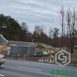
Bridge Approach Polymer Grouting
The Job This bridge approach polymer grouting project is located just outside of Washington, DC. ...
-
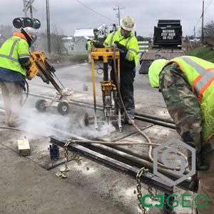
PA Turnpike Undersealing
The Job This PA Turnpike undersealing project is located on the Northeast Extension of the Pennsy...
-
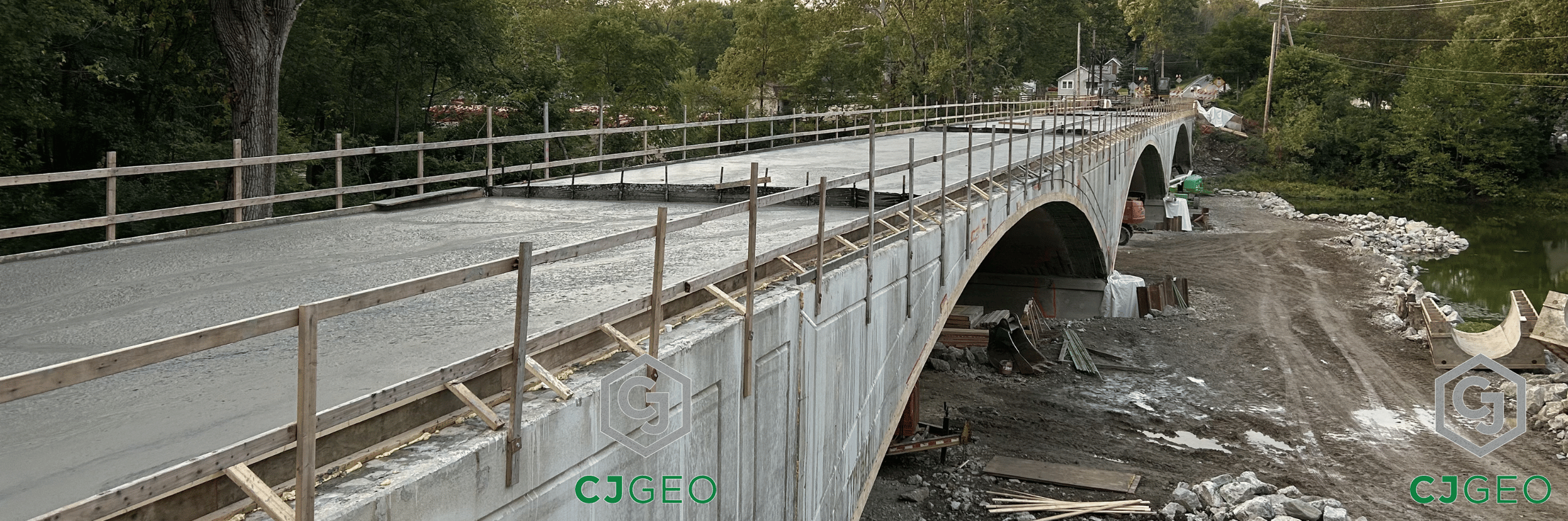
Stone Arch Lightweight Backfill
The Job This stone arch lightweight backfill project is located in Somerset, New Jersey. The ston...
-
MSE Wall Lightweight Backfill
The Job This MSE wall lightweight backfill project is located near Richmond, Virginia. The geotec...
-
Rail Bridge Pier Stabilization
The Job This rail bridge pier stabilization project is located adjacent to the Congaree National ...
-
30k CY Lightweight Embankment
The Job As part of the redevelopment of the Sparrows Point industrial area of Baltimore, three br...
-
Bridge Approach Ground Improvement
The Job This bridge approach ground improvement project by CJGeo is located in Richmond, Virginia...
-
9.5kCY MSE wall backfill
The Job This MSE wall backfill project is located on Interstate 95 north of Baltimore, Maryland. ...
-
Spillway Bridge Grouting
The Job This spillway bridge grouting project is located in Toano, Virginia. Toano is between Wil...
-
North Carolina Tub Crossing Repairs
The Job This tub crossing repairs project is located in Charlotte, North Carolina. Fifty two OldC...
-
CBBT Sheet Pile Pregrouting
The Job This sheet pile pregrouting project is located in the Chesapeake Bay. The Chesapeake Bay ...
-
Garden State Parkway grouting
The Job This Garden State Parkway grouting project is located near Middletown, New Jersey. As par...
-
New Jersey Grade Crossing Stabilization
The Job This grade crossing stabilization project is located in Edison, New Jersey. A precast mod...
-
Veranda St Bridge Infill
The Job This bridge infill work was part of Maine DOT’s Veranda Street Bridge Replacement P...
-
I-64 Soundwall Backfill
The Job VDOT’s I-64 widening project is a multi-phase widening of Interstate 64 between Ric...
-
Illinois Spillway Grouting
The Job A spillway serving as a dam for a lake owned & maintained by a property owner associa...
-
New York Tub Crossing Lifting
The Job Eight panels of StarTrack modular grade crossing tubs settled. As a result of the settlem...
-
NY Grade Crossing Repair
The Job 10 panels of StarTrack modular grade crossing tubs settled in an urban street crossing ow...
-

Sheet Pile Joint Sealing
The Job This sheet pile joint sealing work is part of the Thimble Shoals parallel tunnel project....
-
Massachusetts Lightweight Fill
The Job This Massachusetts lightweight fill project is located at Boston’s Logan Internatio...
-
Box Culvert Void Filling
The Job This box culvert void filling project is located near Fredericksburg, Virginia. The Virgi...
-
Lightweight MSE Wall Backfill
The Job This MSE wall lightweight backfill project is located near Chester, Virginia. The MSE wal...
-
Low Density Bridge Underfill
-
Basement Wall Load Reducing Fill
The Job This basement wall load reducing fill project is located in Lexington, Virginia, on a cam...
-
Maryland Concrete Lifting
The Job This Maryland concrete lifting project is located in Frederick, Maryland. The project is ...
-
Tunnel Adit Fill
The Job This tunnel adit fill project is part of the Purple Line project outside of Washington, D...
-
Electric Bore Annular Space Grouting
The Job This electric bore annular space grouting project is located in Norfolk, Virginia. As par...
-
Bridge Approach Grouting
The Job This bridge approach grouting project is located near Lexington, Virginia. It is on Inter...
-
North Carolina Annular Grouting
The Job This North Carolina annular grouting project is located in Havelock, North Carolina. Have...
-
RCP Joint Sealing
The Job This RCP joint sealing project is located near Charlottesville, Virginia. The polyurethan...
-
Ohio Polyurethane Grouting
The Job This Ohio polyurethane grouting project by CJGeo was for a short line railroad near Scio,...
-
NCDOT pipe abandonment
The Job This NCDOT pipe abandonment project is located outside of Wilmington, North Carolina. It ...
-
NCDOT abandonment grouting
The Job This NCDOT abandonment grouting project is located outside of Chapel Hill, North Carolina...
-
Tunnel Shaft Sinkhole Grouting
The Job This tunnel shaft sinkhole grouting project is located in Newport News, Virginia. It is l...
-
TBM Intervention Permeation Grouting
The Job This TBM intervention permeation grouting project is located in Virginia. It is part of a...
-
T Wall Lightweight Backfill
The Job This T wall lightweight backfill project is located in Boston, Massachusetts. The bridge ...
-
Fort Lauderdale Permeation Grouting
The Job This Fort Lauderdale permeation grouting project is located next to Port Everglades. Port...
-
Slurry Wall Gap Closure Grouting
The Job This slurry wall gap closure grouting work is part of CJGeo’s continuing permeation...
-
Jersey Turnpike Polyurethane Grouting
The Job This Jersey Turnpike polyurethane grouting project is located next to Secaucus Junction i...
-
Lightweight Fill Over Waterline
The Job This lightweight fill over waterline project is located north of Baltimore, Maryland, in ...
-

I95 Philadelphia Lightweight Fill
Backfilling I-95 Bridge Abutments with CJFill-Ultra Lightweight The Job Widening I-95 through Phi...
-
Approach Sleeper Stabilization Grouting
Approach Sleeper Stabilization Grouting The Job CJGeo completed approach sleeper slab stabilizati...
-

Arch Bridge Lightweight Fill
Arch Bridge Lightweight Fill The Job This arch bridge lightweight fill project is located in Fran...