Chemical Grouting Projects
-


Dam Outfall Pipe Seep Grouting
THE JOB This dam outfall pipe seep grouting is located in Fairfax, Virginia at Northern Vi...
-

HDPE Pipe Joint Sealing
THE JOB A large sinkhole opened up in the parking lot of a manufacturing facility. The sinkhole w...
-

Warehouse Floor Water Intrusion Repair
The Job This warehouse floor water intrusion repair project is located in Columbua, South Carolin...
-

Sand Filter Joint Sealing
The Job This sand filter joint sealing project is located in Richmond, Virginia. Two underground ...
-


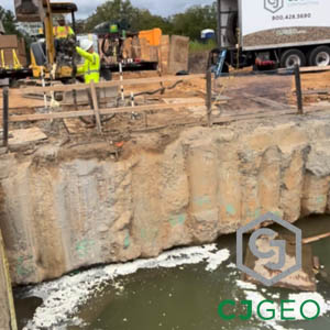
Chemical Underpinning
The Job This chemical underpinning project is located outside of Pittsburgh, Pennsylvania at a ma...
-

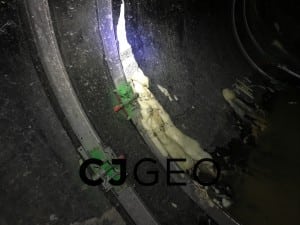
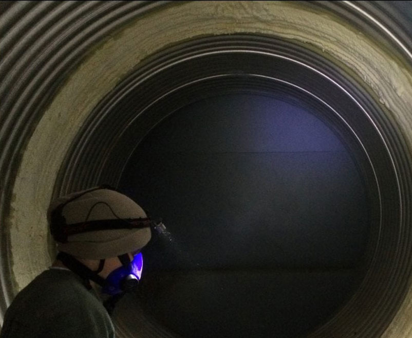
Acid Drainage Grouting
The Job This acid drainage grouting project is located in West Virginia. A 72″ CMP stream d...
-

Toe Drain Abandonment
The Job This toe drain abandonment project is located outside of Washington, DC. Lake Whetstone i...
-

MTBM Recovery Grouting
The Job This MTBM recovery grouting project is located in Florida. When a 42″ MTBM stopped ...
-

Launch Shaft Permeation Grouting
The Job This launch shaft permeation grouting project is located in Fort Myers, Florida. As part ...
-

Hotel Basement Water Intrusion Grouting
The Job This basement water intrusion grouting project was at a hotel in Baltimore, Maryland. It ...
-

Spillway Bridge Grouting
The Job This spillway bridge grouting project is located in Toano, Virginia. Toano is between Wil...
-

Valve Vault Infiltration Grouting
The Job This valve vault infiltration grouting project is part of the Purple Line project in Mary...
-


Sheet Pile Joint Sealing
The Job This sheet pile joint sealing work is part of the Thimble Shoals parallel tunnel project....
-

SOE Closure Manchette Grouting
The Job This SOE closure Manchette grouting project is located in Alexandria, Virginia. It is par...
-

SOE Leak Grouting
The Job This SOE leak grouting project is located in Alexandria, Virginia. It is part of the Rive...
-

Outfall Leak Grouting
The Job This outfall leak grouting project is located near Emporia, Virginia. The work is located...
-

New Jersey permeation grouting
The Job This New Jersey permeation grouting project is located in Elizabeth, New Jersey. It is at...
-
Flooded Shaft Grouting
The Job This flooded shaft grouting project by CJGeo is located outside of Washington, DC at a da...
-

WWTP Tunnel Curtain Grouting
The Job This WWTP tunnel curtain grouting project is located in Syracuse, New York. It is located...
-

Indoor Pool Abandonment
The Job This indoor pool abandonment project is located in West Virginia, at Concord University. ...
-

TBM Intervention Permeation Grouting
The Job This TBM intervention permeation grouting project is located in Virginia. It is part of a...
-

Fort Lauderdale Permeation Grouting
The Job This Fort Lauderdale permeation grouting project is located next to Port Everglades. Port...
-

Slurry Wall Gap Closure Grouting
The Job This slurry wall gap closure grouting work is part of CJGeo’s continuing permeation...
-


Tangier Island Communications Building Slab Stabilization
Tangier Island Communications Building Slab Stabilization The Job The Tangier Island telephone ex...