Permeation Grouting
-

Acid Drainage Grouting
The Job This acid drainage grouting project is located in West Virginia. A 72″ CMP stream d...
-

MTBM Recovery Grouting
The Job This MTBM recovery grouting project is located in Florida. When a 42″ MTBM stopped ...
-
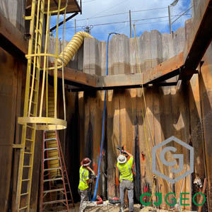
Launch Shaft Permeation Grouting
The Job This launch shaft permeation grouting project is located in Fort Myers, Florida. As part ...
-

Pregrouting for Hand Mining
The Job This large CSO project in Alexandria, Virginia required pregrouting for hand mining. The ...
-

SOE Closure Manchette Grouting
The Job This SOE closure Manchette grouting project is located in Alexandria, Virginia. It is par...
-

SOE Leak Grouting
The Job This SOE leak grouting project is located in Alexandria, Virginia. It is part of the Rive...
-

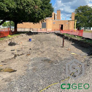
New Jersey permeation grouting
The Job This New Jersey permeation grouting project is located in Elizabeth, New Jersey. It is at...
-

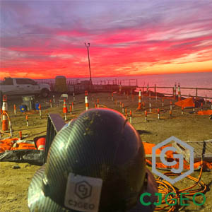
Flooded Shaft Grouting
The Job This flooded shaft grouting project by CJGeo is located outside of Washington, DC at a da...
-
WWTP Tunnel Curtain Grouting
The Job This WWTP tunnel curtain grouting project is located in Syracuse, New York. It is located...
-
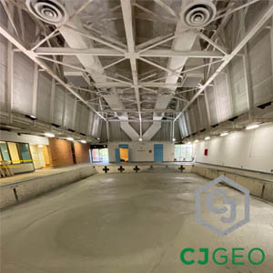
Indoor Pool Abandonment
The Job This indoor pool abandonment project is located in West Virginia, at Concord University. ...
-
TBM Intervention Permeation Grouting
The Job This TBM intervention permeation grouting project is located in Virginia. It is part of a...
-

Fort Lauderdale Permeation Grouting
The Job This Fort Lauderdale permeation grouting project is located next to Port Everglades. Port...
-

Slurry Wall Gap Closure Grouting
The Job This slurry wall gap closure grouting work is part of CJGeo’s continuing permeation...